I started learning to use Arduino this summer and I came up with an idea. I wanted to build a hi speed photography trigger since two but I found it rather difficult building a prototype using analog devices since I didn’t have the necessary skills, tools and workflow.
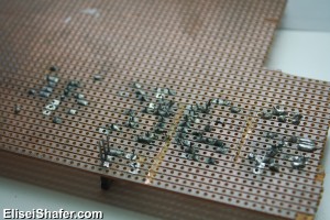
I designed an analog circuit based on sensors and schematics from hiviz.com. I used a stripboard and had plenty of difficulty using the equipment that I had, a cheap $5 soldering iron and cheap solder from dealextreme (without any rosin, ouch!) plus the stripboard that I had was 5 years old and full of oxidation. I couldn’t understand why my solder wouldn’t stick. It was beading around the board and components. I tried using flux but then I understood that I got the wrong kind and the stripboard went green because the flux was eating away at the copper. When I plugged in my board a few of my components cracked and popped, smoke started coming out of the project that I invested hours upon hours of my life in. It was disappointing =[

After I was upset for a few days I thought that my whole approach to this would have to change, I’d need to get better equipment, so I went and bought a temperature controlled soldering iron, rosin core solder, found a PCB manufacturer. I thought that there’s too much soldering involved in analog devices and it was lacking flexibility so I learnt how to program Arduino. This time I would tackle the problem in a professional manner.
Next week I’ll start going through some of the things I learnt when making electronics.

Very nice 😀
Thanks KG =]