Hey guys, I wanted to show you one of my projects: The Comb Jelly Wall Clock. The project was inspired by comb jellies. Comb Jellies live in the sea, they drift around and have strips called comb rows that they use to propel themselves. When white light illuminates the combs an effect called iridescence occurs and we get to see wonderful colours! Check out this video from the Monterey Bay Aquarium:
I wanted to make a clock that’s inspired by the ocean in some way. I also had a bunch of ws2812 aka NeoPixel strips that needed to be exploited. So take those two together and you have a comb jelly clock.
For the body I laser cut a bit of perspex. I also used an Arduino with the Adafruit NeoPixel library without which I don’t think that I’d complete the project =] Wire everything up, upload the programme, connect a power supply and you’re good to go.
So in the end I can say that this is a great project to build and it’s pretty fun to stare at and meditate on, sort of like a fireplace or lava lamp but with many more colours.
If you want any more details feel free to contact me and I’ll get back to you as soon as I can.
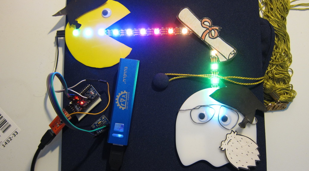
About a year ago I saw that in the States many people decorate their academic caps. Usually they’re full of glitter, some beads and a few words glued onto them. For my graduation I wanted to make something a bit more geeky. I knew that I wanted to have a microcontroller with leds and some sensors attached, but I didn’t know what the story would be about. So I searched on the net and found somebody made a cap with Pacman on it. Great! Now I could add some lights to that concept!
So the whole thing consists of a Chinese Arduino Pro Mini 3.3V knockoff, an ADXL345 accelerometer, an addressable LED strip (WS2812) and, of course, a power source. The power source proved to be a bit of a problem because the adxl works on 3.3V and the strip works on 5. I didn’t have a lot of components and batteries lying around so in the end I took a 5V backup battery for cellphones and connected it to an FTDI breakout board which in turn powered the Arduino (3.3V). I also soldered a wire from 5V of the board to the LED strip.
The cool thing about the ADXL345 is that it has motion detection, tap + double tap sensing and freefall detection all built in. So I utilised that in my project. Double tap to turn it on and off, when the accelerometer senses that you’re active the lights run and when your’re still the lights stay still. When tapped once the cap goes into rainbow mode.
I have to say that it would have been very, very difficult to get this project finished without the help of some libraries. For the LED strip I used the Adafruit NeoPixel library. For the adxl tap sensing I used this library from bildr.org.
This is part of a bigger project I’ve been wanting to build for quite some time, the sunrise alarm clock . A “sunrise alarm clock” or, as wikipedia calls it, a “dawn simulation alarm clock” is the same as a regular alarm clock only it has a light that gradually brightens over a period of half an hour before you wake up, thus you tend to wake up more refreshed.
There are a lot of sunrise alarm clocks out there but I thought I’d make one with a twist. Since I use my smartphone as an alarm clock what would be better than setting an alarm on my phone and let it do the communication with the light. This has the added advantage of mobility, I can set the light wherever I want and move it later if it doesn’t suit my needs. On the hardware side I also wanted the freedom to experiment with different types of lights (even though they’ll all be incandescent), so I made it with a plug and socket.
There are 3 main parts to this project. The dimmer, the MCU (Arduino) and the Bluetooth module (HC-06). I won’t go into too many details as there are plenty of resources on the net that I’ll give links to.
Arduino Pro Mini and the HC-06 Bluetooth module.
The dimmer works just like a regular dimmer only that it’s triggered by the MCU. I built a circuit based on this instructable by diy_bloke.
For the MCU I wanted to use the attiny85 with Arduino bootloader but I found out the hard way that it only has one interrput and no dedicated serial communication. That meant that it could either communicate through UART or it could work the dimmer, but not both. So I ended up using an Arduino Pro Mini for the MCU.
The Bluetooth module is an HC-06. It uses the SPP protocol to emulate a serial cable. Basically the MCU thinks that it’s using a regular serial cable to communicate when in fact it’s communicating over bluetooth. You can get it for around 6 bucks off ebay. Here’s an excellent resource on the module by Erich Styger. Although it’s not for Arduino it still has a lot of useful info.
Dimmer is controlled by phone via bluetooth
The bluetooth dimmer unplugged. It’s designed for any incandescent light up to 300W.
The box open. Circuit boards are wrapped in shrink tubing.
AC power supply can be seen at the bottom of the box. The black thing sticking out of the box is the fuse.
Arduino Pro Mini and the HC-06 Bluetooth module.
First tests
The board has the dimmer circuit at the top. bottom left: ICSP header for original MCU. Original MCU didn’t fit needs so the header was later removed. bottom middle: space for the original MCU, wires were later soldered to an Ardunio. Bottom right wires to Bluetooth.
A wall wart power supply stripped of it’s casing. 220V~ to 5V DC
Last month I entered the Red Sea 2014 underwater photography competition. The competition was pretty tough, even in the amateurs category, and I had two school projects to finish on the same week as the competition, so as you can imagine I didn’t do pretty well in either =[ On the other hand I did get a pretty good shot that you can see here:
Hugs. Shot with Canon S5IS with flash.
Here are some more pictures I took from the competition:
Hugs. Shot with Canon S5IS with flash.
I really have to many of these =]
P.S. you can check out the winners of this year’s competition here.
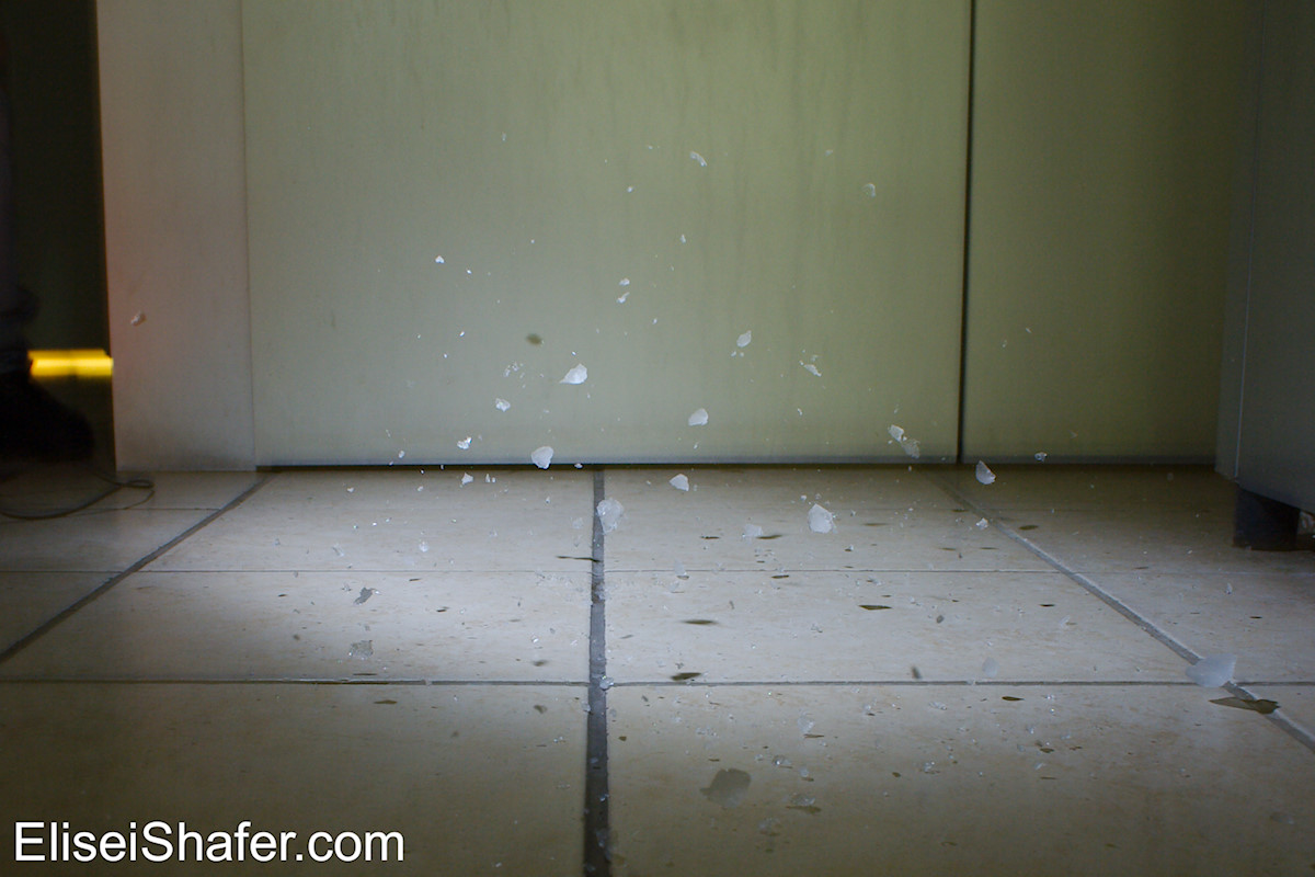
Ever since I built my high speed photography trigger I’ve been putting off taking photos…until now! Julia and I had some fun experimenting with the trigger.
The setup wasn’t all too difficult but does require some planning. First I had to collect some light bulbs for smashing, buy a background and find some other interesting stuff to shoot. Next we had to setup the lighting; we found that lighting from the top and the side worked out pretty well. After that, calibrate the camera’s and we’re done! (at least with the setup 🙂
When everything was ready we started shooting =D Time to get rid of some of those burnt out, energy wasting lightbulbs!
high speed photo of a balloon being cut by a kitchen knife.
high speed photo of tomatoes being crushed by a hammer
High speed photo of falling water balloons hitting ground.
High speed photo of a balloon popping because of over inflation.
High speed photo of balloon being popped by hammer.
High speed photo of light bulb being hit by hammer.
High speed photo of Lightbulb being shattered by hammer.
High speed photo of Lightbulb being smashed to bits by hammer.
Behind the scenes
The circuit that I designed and built for high speed photos
AgIC are making a kickstarter project that lets you print an circuits using an inkjet printer. One big application that I can see is prototyping PCBs before you send them out for manufacturing, this could be a huge hit for makers and whoever’s into making and selling circuits in small volumes.
There are other rapid prototyping methods out but they’re either messy, expensive or both. They usually involve either acid etching, CNC milling or paying a company lots of money to ship you the board overnight. In all cases it takes time to make the board, in the former cases you’d have to have a setup that takes a lot of space and makes a mess. The guys at AgIC have found a way to make circuits clean and easy.
In their video on kickstarter they showed how you can use their product and do away with breadboards altogether. You can design your circuit on your computer using your favourite board design software, print it out, attach components and you have a working board.
For some reason their campaign isn’t getting a lot of traction. I mean a button for a smartphone got 700k. These guys as of writing this post have only 70k.
I just hope that they’ll make it and the price point of the inkjet cartridges will be low enough for me to buy them =]
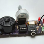
Hey guys, for those of you that don’t know I’ve got exams coming up in the middle of exams. It’s a crazy time* and I’ve had to put off the second part of my soldering tutorial until I at least next week when I finish my heat transfer exam. I did find some time to shoot a few pictures, nothing to write home about but enough to test out my sound trigger.
*I’ve even been sent an email from the dorms office that there’s a guy running round naked in the campus, how about that?
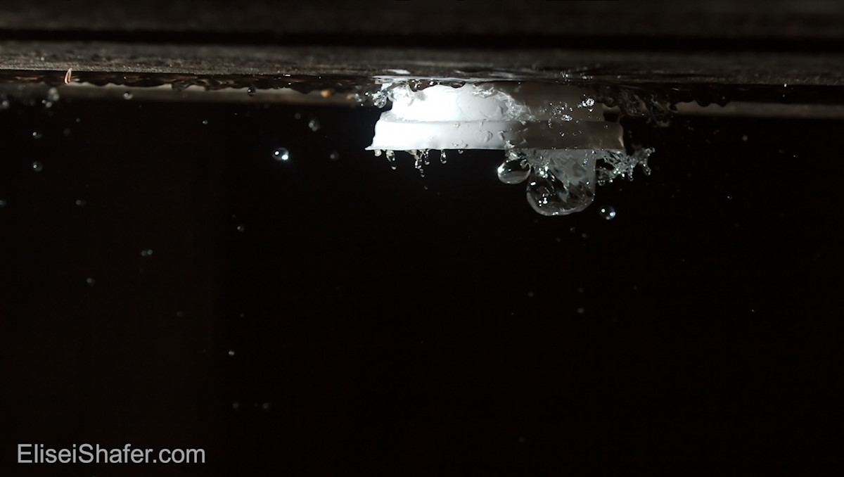
In the beginning I didn’t know what to do with the sound trigger, except pop a few balloons to test it’s speed. After doing that I didn’t really know where I could go with it. Julia, my girlfriend, suggested that we go outside to photograph. She wanted to do regular night photography, but I knew that this was my chance to test out the sound trigger =P So with the sound trigger, a couple of cameras and strobes we went outside and went outside and got this shot.
If you’re wondering what this is, it’s a coffee cup lid with water in it upside-down. When looking for stuff to shoot Julia came across a used coffee cup. We poured water into the lid, placed it on the table and kicked it. It gives a nice effect of water flying around.
Later I want to take photos breaking something with glass, but, at least for now, glass is messy and I don’t want to keep looking for glass bottles. Next best thing? Ice! Also breaks but only leaves water behind =]
I know, kind of crappy, but hey, this was done in the middle of studying for an exam!
Last week I talked about how I tried to build a prototype flash trigger. One of the skills that I lacked was how to solder. My dad used to fix TV’s for a living and I thought how hard could it be? It isn’t that hard, but you’ve got to know what you’re doing. There’s science and art behind soldering. There are many tutorials on the net, but I thought that I’d add one of my own. This is one of the skills that they didn’t teach me in high school and university.
I thought that I’d do this in one go but it turns out that a detailed tutorial is better done in parts.
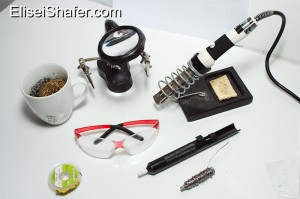
Equipment
Top:Brass shavings in cup, helping hands with magnifying glass, Soldering iron with stand. Bottom:Solder wick, safety glasses, solder sucker solder.
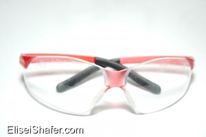
Safety glasses.
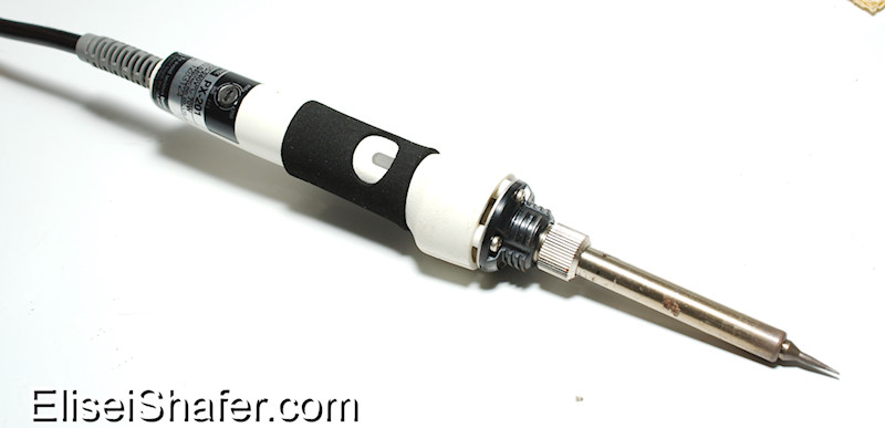
A temperature controlled soldering iron.
Rosin-core solder
Wet sponge or brass sponge.
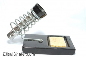
A solder stand.
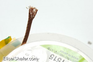
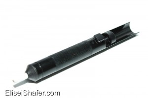
Solder wick or solder sucker aka solder pump.
Third hand aka helping hands. Not as essential, but highly recommended.
Links
If you find my post useful, please consider supporting my website using these links:
Hakko Soldering iron – an excellent choice for beginners, better than the one used here.
Safety
Wear your safety glasses! Irons get hot and whatever you’ll be soldering will be pretty close to you. Plus solder sometimes spews out tiny balls when you heat it.
Solder in a well ventilated area. Solder fumes are hazardous; They contain lead and rosin that are harmful. You can also get yourself a fume extractor with a carbon filter if you solder a lot.
Use a solder stand. Again, irons are hot, which makes them a fire hazard.
Temperature controlled soldering iron
Temperature controlled soldering iron. Note the dial near the back end of the soldering iron.
Why temperature controlled? If you get a cheap iron that has no temp control the tip will get heated to a temperature much greater than the melting point of the solder. You want your iron to be a bit hotter than the melting point of the solder otherwise your iron tip will start getting oxidised really fast which means your iron won’t transfer heat at a good rate, i.e. it won’t melt solder. Other things to look at when buying a soldering iron:
Soldering Station or . If you have the space and money , get a soldering station. If you don’t have the money and space or/and you’d like a more portable system you can get an iron with a temperature control dial built in. I bought a soldering iron without a station because I’m a student short on money and space.
Wattage: I read that 15-40W is enough for electronics, more than that you can damage components. If you use a temperature controlled iron you can get away with more (mine’s 70W) . I’d go for a higher wattage so long as there are tips available for finer work. If you get a weaker iron you may not be able to solder bigger components like connectors or PCB pads with higher heat mass.
Look at the tip a flat or round tip should be ok. Also check the availability of tips. You don’t want to buy an iron only to find out later that there aren’t any replacement tips!
Solder
Rosin core solder. Note the hole in the middle of the solder, that’s the rosin core. Diameter of this solder is around 0.8mm.
There are many types of solder available, there are variations on alloys, fluxes and number of cores.
I use 60/40 solder. 60/40 refers to the percentages of tin and lead, respectively, in the solder. Lead solder is being phased out of commercial products because of health concerns and regulations but I’ve heard that its easier to work with. Lead free solder typically has a higher melting point which means that you’ll need to heat components to a higher temperature and that in turn increases the chance of damaging them.
Flux removes the metal oxide off of the components you’re soldering. If you don’t have flux then your solder won’t stick and will ball up. You can get rosin core solder or one of the newer water based fluxes.
Core refers to the number of flux cores in the solder. There are multicore solders available, but personally I use 1 core solder, it works for me.
Sponge
Wipe your solder iron tip on this to remove oxidation.
You’ll need you clean oxidation off of your tip before you solder a component so that the joint will be clean and to have better heat transfer. Wet sponge or brass sponge (brass shavings), your choice, both of them work. There are many an argument on the net about which one is better, uses, etc.
Solder Stand
Soldering Iron Stand. Note the yellow sponge.
If you buy one of the more expensive irons you’ll probably get a stand included. Cheaper irons don’t come with a stand.
I’d get a stand where you can’t touch the hot part of the iron by accident. A lot of stands come with a place to put your sponge so look out for those.
Solder wick and Sucker
Solder sucker sucks up molten solder to release your components
If When you make a mistake soldering or if you want to recycle components from your old radio/TV you’ll need a solder sucker or wick.
A solder sucker has a spring loaded mechanism that when triggered sucks up your molten solder. Good for through hole components.
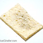
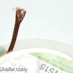
A solder wick can be used for smaller components and whenever you’ll want to clean up a mess. It’s basically braided copper wire treated with chemicals. It works through surface tension and wick up your mess.
Helping hands
With these hands you’ll be able to solder wires without frustration. The magnifying glass will help when soldering smaller components =]
This will hold the things that you’ll want to solder in place. Say for example you want to solder two wires then you’ll need to hold both the wires, solder and iron, four things you’ll need to hold! That’s where helping hands come in. They hold the wires for you so that you can focus on the soldering.
Next week we’ll learn how to use these tools =D
Feel free to email me and leave comments.
Here’s a gallery with bigger photos.
Top:Brass shavings in cup, helping hands with magnifying glass, Soldering iron with stand.
Bottom:Solder wick, safety glasses, solder sucker solder.
Temperature controlled soldering iron. Note the dial.
Soldering Iron Stand. Note the yellow sponge.
Rosin core solder. Note the hole in the middle of the solder, that’s the rosin core. Diameter of this solder is around 0.8mm.
Wipe your solder iron tip on this to remove oxidation.
Solder sucker sucks up molten solder to release your components
With these hands you’ll be able to solder wires without frustration. The magnifying glass will help when soldering smaller components =]
I started learning to use Arduino this summer and I came up with an idea. I wanted to build a hi speed photography trigger since two but I found it rather difficult building a prototype using analog devices since I didn’t have the necessary skills, tools and workflow.
I designed an analog circuit based on sensors and schematics from hiviz.com. I used a stripboard and had plenty of difficulty using the equipment that I had, a cheap $5 soldering iron and cheap solder from dealextreme (without any rosin, ouch!) plus the stripboard that I had was 5 years old and full of oxidation. I couldn’t understand why my solder wouldn’t stick. It was beading around the board and components. I tried using flux but then I understood that I got the wrong kind and the stripboard went green because the flux was eating away at the copper. When I plugged in my board a few of my components cracked and popped, smoke started coming out of the project that I invested hours upon hours of my life in. It was disappointing =[
Cold joints everywhere, I’ve since improved my soldering skills.
After I was upset for a few days I thought that my whole approach to this would have to change, I’d need to get better equipment, so I went and bought a temperature controlled soldering iron, rosin core solder, found a PCB manufacturer. I thought that there’s too much soldering involved in analog devices and it was lacking flexibility so I learnt how to program Arduino. This time I would tackle the problem in a professional manner.
Next week I’ll start going through some of the things I learnt when making electronics.


![With these hands you'll be able to solder wires without frustration. The magnifying glass will help when soldering smaller components =]](http://eliseishafer.com/wp-content/uploads/2014/01/IMG_9321_1-199x300.jpg)


![With these hands you'll be able to solder wires without frustration. The magnifying glass will help when soldering smaller components =]](http://eliseishafer.com/wp-content/uploads/2014/01/IMG_9321_1-150x150.jpg)

